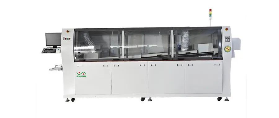
 Description Wave soldering is a common electronic device, so how much do you know about its working principle? This article will introduce you to the working principle of wave soldering and the internal structure diagram of wave soldering. Wave soldering Wave soldering is to let the welding surface of the plug-in board directly in contact with high-temperature liquid tin to achieve the purpose of welding, the high-temperature liquid tin to maintain a slope, and by a special device to make the liquid tin form a wave-like phenomenon, so called "wave soldering", its main material is solder bar. Wave soldering working principle Wave soldering machine is mainly composed of transportation belt, flux adding area, preheating area, and tin furnace. The main purpose of the transport belt is to feed the circuit base into the wave soldering machine, passing through the flux adding area, the preheating area, and the furnace. The flux adding area is mainly composed of infrared sensors and nozzles. The infrared sensor is used to sense whether there is a circuit board entering, and if there is a sensor, the width of the circuit board will be measured. The flux is used to form a protective film on the soldering surface of the circuit board. The preheat zone provides enough temperature to form a good solder joint. There is infrared heat generation for uniform heating of the circuit board. In the dual wave system, the turbulent part of the wave prevents leakage and it ensures proper solder distribution across the board. The solder penetrates through the slit at a high speed and thus penetrates the narrow gap. The direction of injection is the same as the direction in which the board proceeds. The turbulent wave alone does not properly solder the component; it leaves unevenness and excess solder on the solder joint, so a second wave is needed. The second laminar or smoothing wave eliminates the burrs and solder bridges created by the first turbulent wave. The laminar flow wave is actually the same wave used in conventional through-hole cartridge assemblies. Therefore, when a conventional component is soldered on a single machine, the turbulent wave can be turned off and the conventional component can be soldered with the laminar wave. Diagram of wave soldering system
 The most commonly used dual-peak system on the market today has a turbulent wave that moves reciprocally, with solder ejected from a nozzle rather than from a narrow slit. A moving nozzle is more effective than a slit in preventing solder leakage because it not only generates turbulence but also has a cleaning effect.
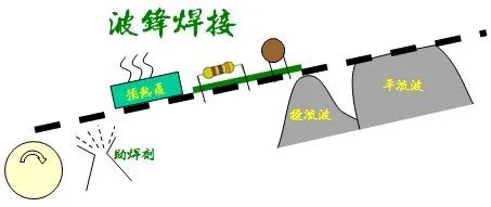
Wave Soldering Technology
The figure below shows the soldering technique of wave soldering, where the molten solder in the solder pool is ejected upwards to form a projecting waveform. During the soldering process, a PCB (PCBA) with a component inserted is coated with solder, preheated, and then passed through a waveform formed by the melted solder, so that the PCB touches the top of the waveform and the connection between the component and the PCB pad is soldered.
There are many types of wave soldering systems, depending on the geometry of the machine used.
Dual wave soldering systems
Shown is one of the wave soldering systems (dual wave soldering system), where the first wave is a turbulent wave, which serves to prevent false soldering. The second wave is a smoothing wave that helps eliminate burrs and bridges. Turbulence is created either by passing the molten solder through an oscillator or by injecting nitrogen into the solder pool.
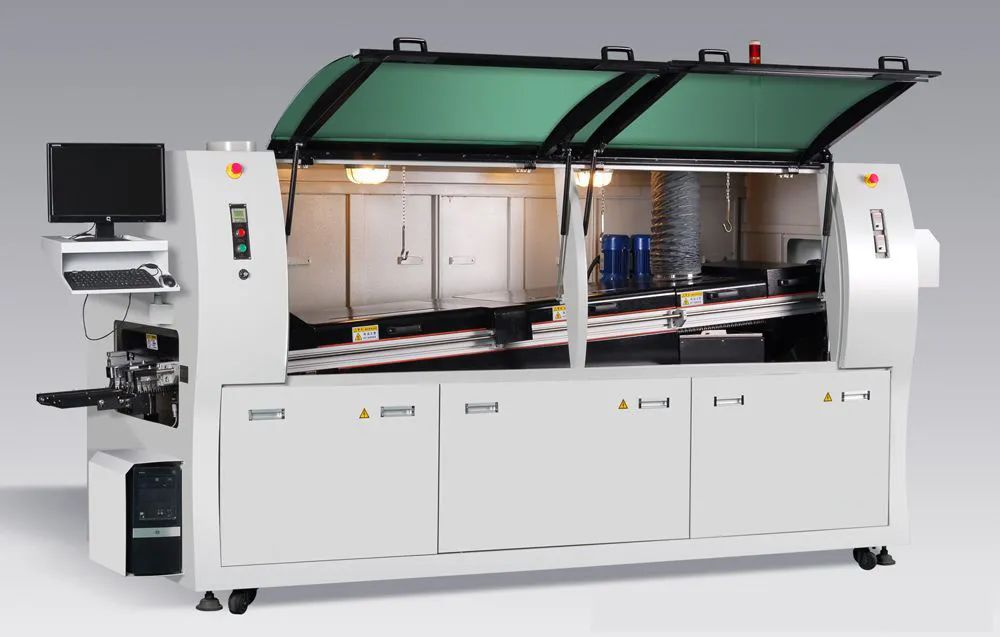
Diagram of the internal structure of wave soldering
The internal structure of wave soldering consists of five main components
Spray system
Preheating system
Soldering system
Cooling system
Transport system
Routine maintenance and care of wave soldering
Wave soldering operators must maintain and service the machines from time to time to ensure the safety of personnel and equipment, normal operation and product quality, reduce equipment failure and avoid accidents. So the operator must do the following points:
1, the equipment must always keep the hot air, cooling, transmission, wave and other motor shell clean for heat dissipation;
2, regularly check the tin furnace, pre-heater in the heater connection, such as found loose, poor contact, insulation aging and other phenomena should be tightened, cleaned, replaced; should always check whether the equipment grounding is good;
3, in the event that the power switch should first stop the tin furnace, preheater and wave and other high-current load before opening and closing;
4, wave motor is not rotating, manual speed control is prohibited to prevent damage to the speed control mechanism; melting solder and adding high-temperature liquid solder to the furnace process, you need to wear the necessary protective equipment to prevent burns;
5, the transmission parts should be kept well lubricated, in addition to the angle adjustment mechanism can be used for ordinary grease, the rest of the application of high-temperature grease lubrication;
6, regularly check the wave motor lubrication and operation, to ensure its normal operation; tin furnace nozzle cleaning once a week, so as not to block the nozzle due to debris and affect the smoothness of the wave;
Wave soldering daily spot check
Check the flux hood filter and remove excess flux residue, clean the flux filter once a week with TENNA water, clean the inside of the extraction hood once a week, and check the spray system to see if the spray is even. The nozzle should be cleaned every day, the method is to add alcohol to the smaller flux cartridge, open the ball valve, close the ball valve of the larger flux cartridge, start spraying for 5-10 minutes, take off the nozzle every week, soak it in tenna water for two hours, check whether the tin furnace oxidation black powder, oxidation slag is too much. 1. To reduce the generation of oxide in the tin furnace, you can add anti-oxidation oil, soybean oil, non-oxidizing alloy, etc. in the tin furnace 2. equipment every 1 hour of operation, should check the number of tin furnace oxide black powder, and use the soup funnel to fish out the tin slag 3. Check whether the wave soldering wave is smooth, 200H thoroughly clean the tin furnace once 4. Too much oxide buildup in the tin bath will cause unstable wave seal, tin bath bubbles, and even motor stalls and other problems 5. At this time, you can loosen the screws that fix the spout, the spout will be removed, fishing to remove the spout internal tin slag can be 6. Tin tank solder in the use of several months, the alloy composition will change, affecting the quality of welding, when the solder should be replaced Note The operation of this equipment is strictly prohibited without training personnel, the equipment must be checked before the start of the transmission chain for debris, equipment operation to check the transmission chain at any time whether there is a card chain phenomenon, found card chain to deal with in a timely manner, equipment operation to monitor other parts of the equipment for abnormalities, problems found to deal with in a timely manner, the equipment stops running, to the equipment for 5S finishing, absolutely no flux drops into the preheat box, the tin furnace, electric box and other high-temperature places, which can easily cause a fire every day before the machine should check the amount of solder in the furnace to ensure that the amount of solder is enough, it is strictly prohibited to add tin before shutting down the machine, which is easy to produce the explosion of tin in the next time the machine is turned on attention to keep the internal cleanliness of the electric box to avoid electrical accidents, in adjusting the height of wave soldering, should press the "emergency stop "button, protect the site, notify the relevant personnel maintenance.
Conclusion About the wave soldering principle of operation and its internal structure is introduced here, I hope this article can help you, if there are deficiencies welcome to correct.


 Description


